
Page 12 - March 2023
P. 12
PAID ADVERTISER CONTENT
Why the Evolution to
Propellers with More Blades?
by Martin Albrecht (President, MT Propellers) | Provided by BLR Aerospace
With the improvement in materials and Computational Fluid Dynamics (CFD) software, the trend toward more blades on propellers is clear. From the original standard of 3-blade propellers, technological advancements have allowed for the development of 5-blade or even 7-blade propellers, which are increasingly common for turboprop applications.
Classic propellers were made with hubs from steel and utilized aluminum blades. Propellers with more than three blades or even five blades, were not possible because of engine and airframe limitations due to the limiting factor of their weight.
With the availability of newer materials, the transition to propellers made with light-weight aluminum hubs combined with light-weight composite blades was made possible. Composite blades can now be made from a special high strength, plasticized structural wood combined with carbon fiber layers or a foam core wrapped with carbon fiber.
These new materials allowed for four, five or even seven-blade pro- peller systems with minimal increases in the overall weight. Addition- ally, with lighter weight blades, a reduction of gyroscopic moment lowers the loads on the engine/airframe by up to 40%.
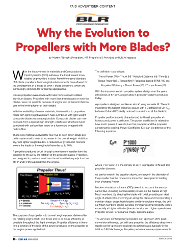
A propeller produces thrust through a momentum transfer from the propeller to the air by the rotation of the propeller blades. Propellers are designed to produce maximum thrust from the torque (a function of HP and RPM) supplied from the engine.
The purpose of a propeller is to convert engine power, delivered by the rotating engine shaft, into thrust and to do so as efficiently as possible throughout the flight envelope. Propeller efficiency is there- fore a function of the ratio of the power produced by the propeller to the engine power applied to it.
The definition is as follows:
Thrust Power [W] = Thrust [N] * Velocity ( Distance [m] / Time [s] )
Torque Power [W] = Torque [Nm] * Rotational Speed [RPM] / 60 sec Propeller Efficiency = Thrust Power [W] / Torque Power [W]
With the improvements in propeller system design over the years, efficiencies of 87-90% are possible in propeller systems produced today.
A propeller is designed just like an aircraft wing to create lift. The opti- mum lift for the highest efficiency occurs with a Coefficient of Lift (CL) between 0.4 and 0.7, ideally reduced to a minimum at the blade tip.
Propeller performance is characterized by thrust, propeller ef- ficiency and power coefficient. The power coefficient is related to how much power it takes to turn the propeller and the propeller aerodynamic loading. Power Coefficient (CP) can be defined by the following equation:
where P is Power, z is the density of air, N is propeller RPM and D is propeller diameter.
As can be seen in the equation above, a change in the diameter of the propeller has five times more impact on aerodynamic loading than changing Power.
Modern simulation software (CFD) takes into account the aerody- namic flow, including compressibility losses on the blades at high Mach numbers. By shaping the blade with twist, providing an ideal angle of attack with oncoming air along the blade and incorporating a scimitar shape, swept-back blades similar to airplane wings, the criti- cal Mach numbers can be avoided, minimizing compressibility losses especially at higher altitudes (low air density) and higher speeds (see Propeller Cruise Performance image, opposite page).
The very best contemporary propellers can approach 90% peak conversion efficiency, but with any propeller, the efficiency drops very rapidly as the tip velocity exceeds its optimal value, typically in the 0.84 to 0.88 Mach range. Propeller performance maps (see example
10 • KING AIR MAGAZINE
MARCH 2023
