
Page 13 - March 2023
P. 13
PAID ADVERTISER CONTENT
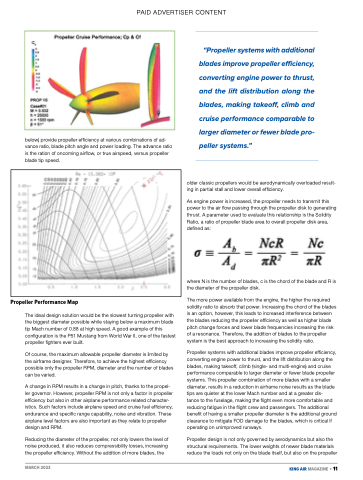
below) provide propeller efficiency at various combinations of ad- vance ratio, blade pitch angle and power loading. The advance ratio is the ration of oncoming airflow, or true airspeed, versus propeller blade tip speed.
“Propeller systems with additional blades improve propeller efficiency, converting engine power to thrust, and the lift distribution along the blades, making takeoff, climb and cruise performance comparable to larger diameter or fewer blade pro- peller systems.”
older classic propellers would be aerodynamically overloaded result- ing in partial stall and lower overall efficiency.
As engine power is increased, the propeller needs to transmit this power to the air flow passing through the propeller disk to generating thrust. A parameter used to evaluate this relationship is the Solidity Ratio, a ratio of propeller blade area to overall propeller disk area, defined as:
where N is the number of blades, c is the chord of the blade and R is the diameter of the propeller disk.
The more power available from the engine, the higher the required solidity ratio to absorb that power. Increasing the chord of the blades is an option, however, this leads to increased interference between the blades reducing the propeller efficiency as well as higher blade pitch change forces and lower blade frequencies increasing the risk of a resonance. Therefore, the addition of blades to the propeller system is the best approach to increasing the solidity ratio.
Propeller systems with additional blades improve propeller efficiency, converting engine power to thrust, and the lift distribution along the blades, making takeoff, climb (single- and multi-engine) and cruise performance comparable to larger diameter or fewer blade propeller systems. This propeller combination of more blades with a smaller diameter, results in a reduction in airframe noise results as the blade tips are quieter at the lower Mach number and at a greater dis-
tance to the fuselage, making the flight even more comfortable and reducing fatigue in the flight crew and passengers. The additional benefit of having a smaller propeller diameter is the additional ground clearance to mitigate FOD damage to the blades, which is critical if operating on unimproved runways.
Propeller design is not only governed by aerodynamics but also the structural requirements. The lower weights of newer blade materials reduce the loads not only on the blade itself, but also on the propeller
Propeller Performance Map
The ideal design solution would be the slowest turning propeller with the biggest diameter possible while staying below a maximum blade tip Mach number of 0.88 at high speed. A good example of this configuration is the P51 Mustang from World War II, one of the fastest propeller fighters ever built.
Of course, the maximum allowable propeller diameter is limited by the airframe designer. Therefore, to achieve the highest efficiency possible only the propeller RPM, diameter and the number of blades can be varied.
A change in RPM results in a change in pitch, thanks to the propel- ler governor. However, propeller RPM is not only a factor in propeller efficiency but also in other airplane performance related character- istics. Such factors include airplane speed and cruise fuel efficiency, endurance and specific range capability, noise and vibration. These airplane level factors are also important as they relate to propeller design and RPM.
Reducing the diameter of the propeller, not only lowers the level of noise produced, it also reduces compressibility losses, increasing the propeller efficiency. Without the addition of more blades, the
MARCH 2023
KING AIR MAGAZINE • 11
